LoRa Rain Gauge
Rain gauge upgraded to LoRaWAN radio technology
While looking for a rain gauge for my IoT weather station, I came across the TFA Dostmann rain transmitter 30.3161, which is very popular in the DIY community. It is offered as a spare part for a weather station for around 20€. There are different approaches to decode the original radio protocol, but unfortunately they always require a separate receiver, which I don't like.
LoRaWAN is becoming widely popular for energy-saving sensor technology in the Internet of Things. The transmission protocol features low power consumption (batteries often last for years) and long ranges (even in urban areas, 1 km can be covered without any problems).
Gateways in the area forward all received data packets to a central server, which then decodes them and makes them available to the owner of the device for further processing. One example of such a public network stack is The Things Network. I already have a LoRaWAN gateway for this. So why not replace the inner components of the rain gauge? An ideal project for a new LoRa sensor was found.
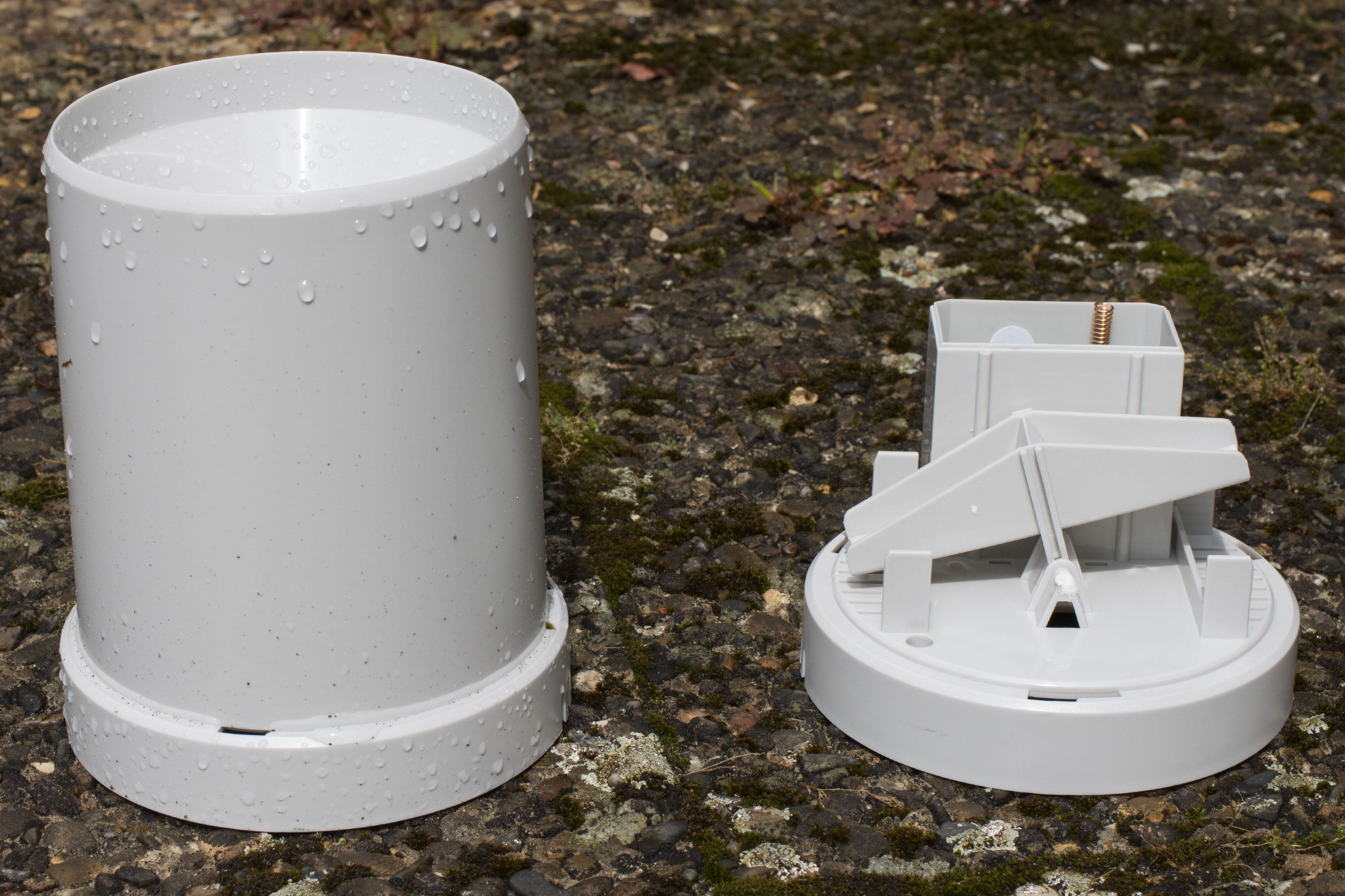
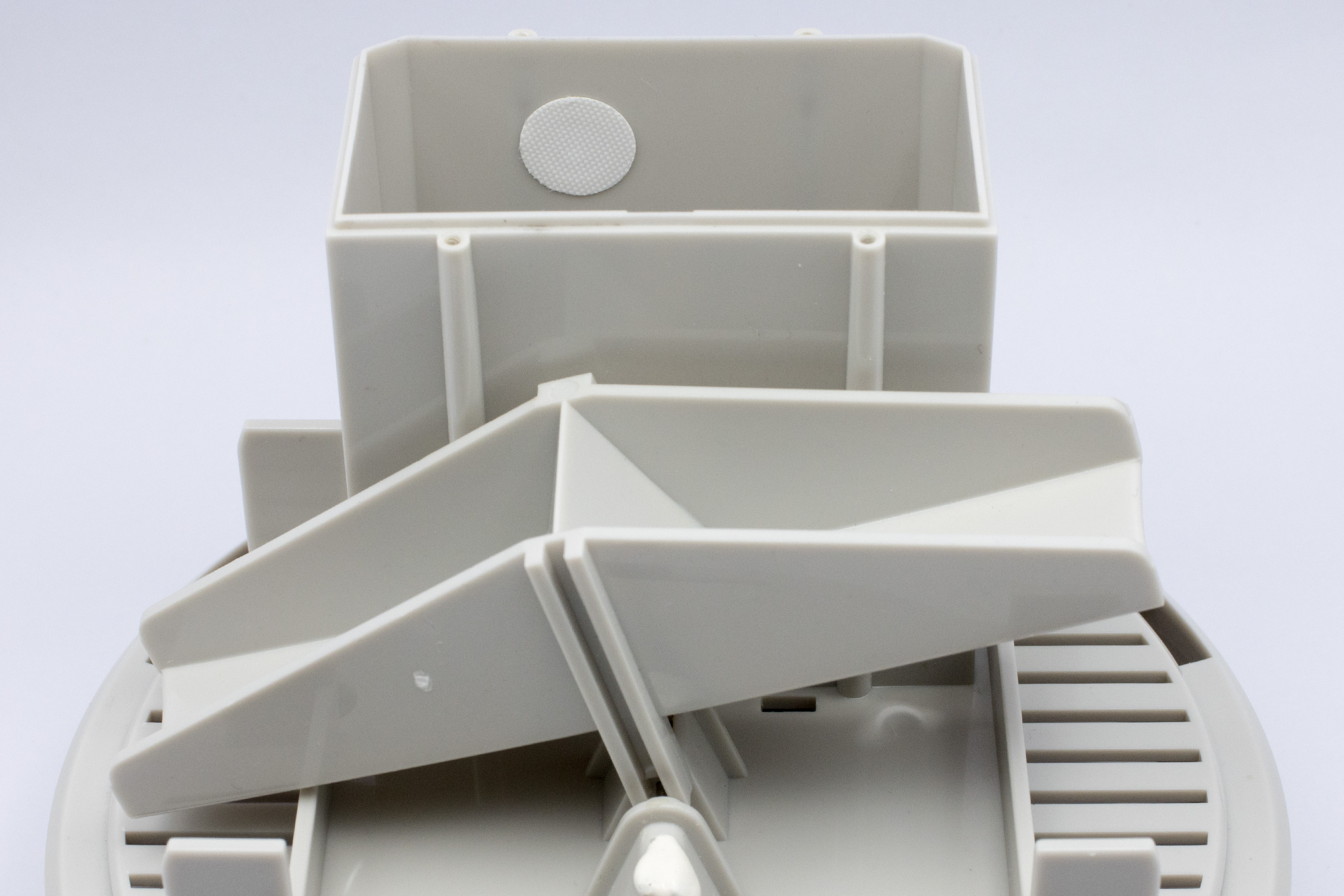
The operating principle of the rain gauge is simple: a funnel collects the rain on a defined area and directs it onto a rocker with two buckets. A rainfall of 0.45 mm causes the water to tip over the seesaw. The other bucket then fills up, while the liquid in the bucket below drains away. A small permanent magnet is attached to the outer edge in the middle of the rocker. This triggers a reed contact on the main circuit board, where the pulses are counted.
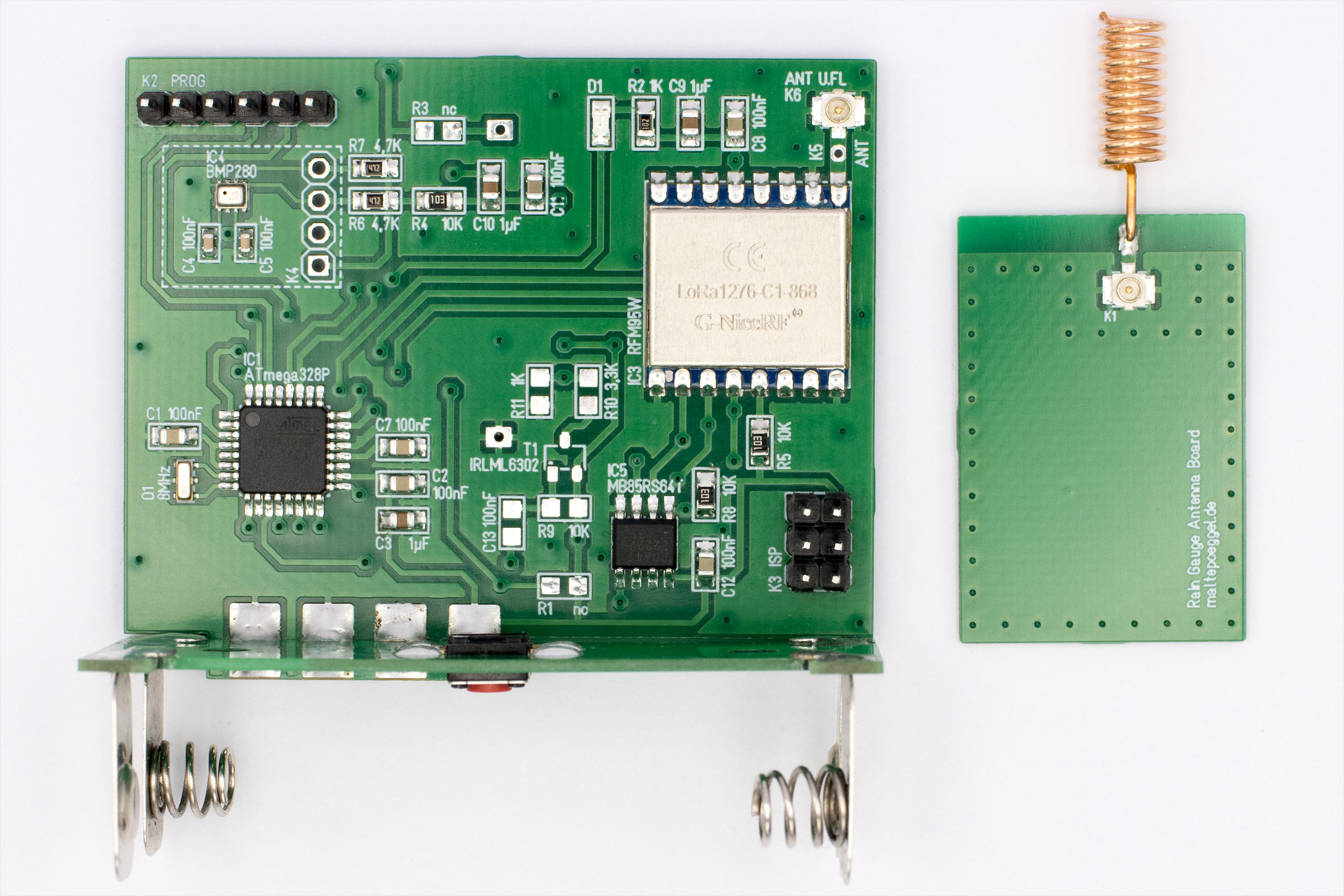
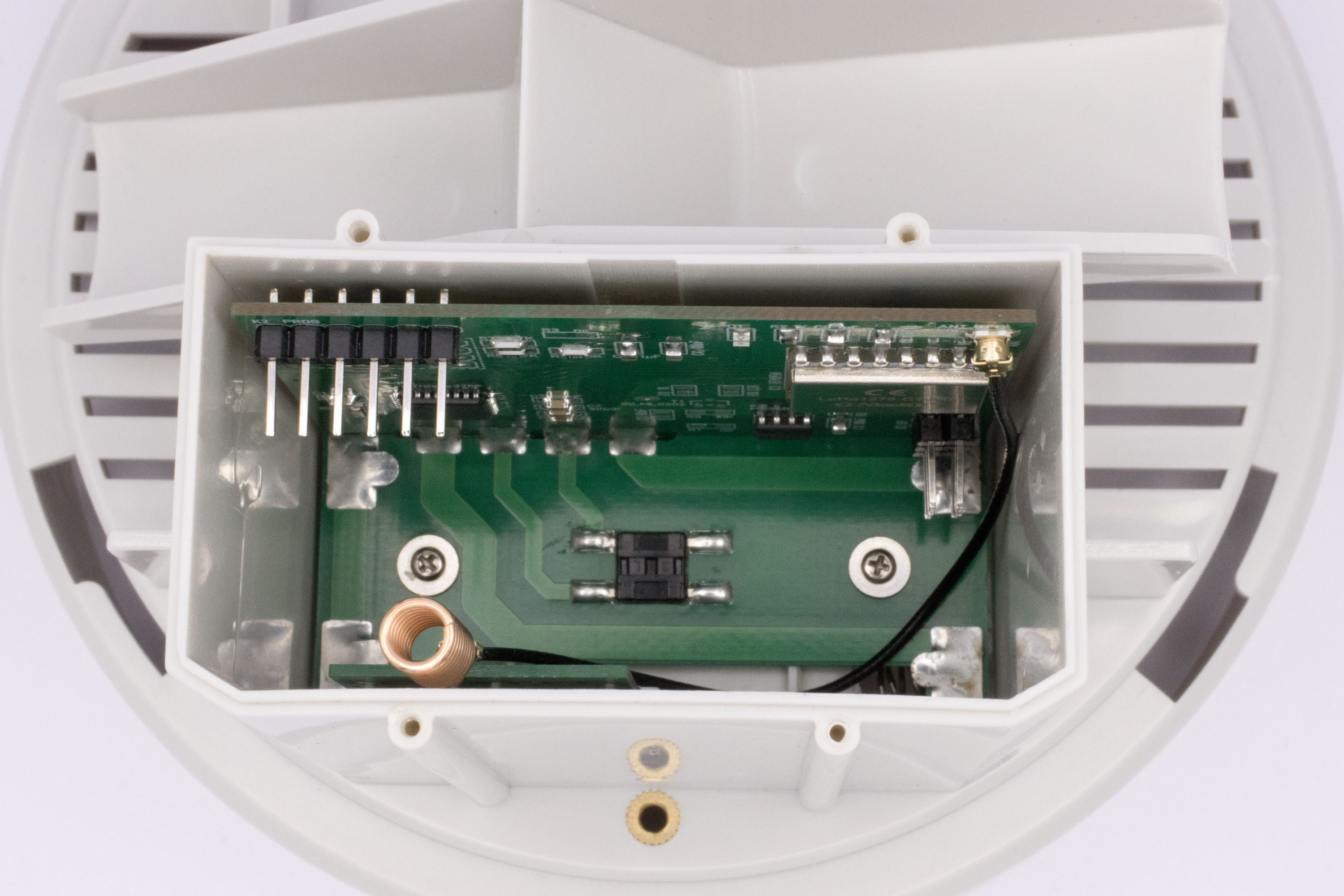
In the inside, the sensor consists of three circuit boards with a thickness of 1.0 mm. One with battery contacts for 2x AA batteries and a button, a main board and a transmitter board with antenna. The mechanical dimensions are quickly taken up, everything is redesigned. The battery board remains similar, the new transmitter board only serves as a holder for the antenna. The new microcontroller and all peripherals are located on the main board. Only the battery contacts are reused, as the old reed contact is bistable and the antenna is designed for a different frequency range.
Circuit description
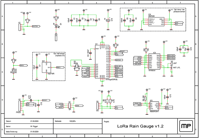
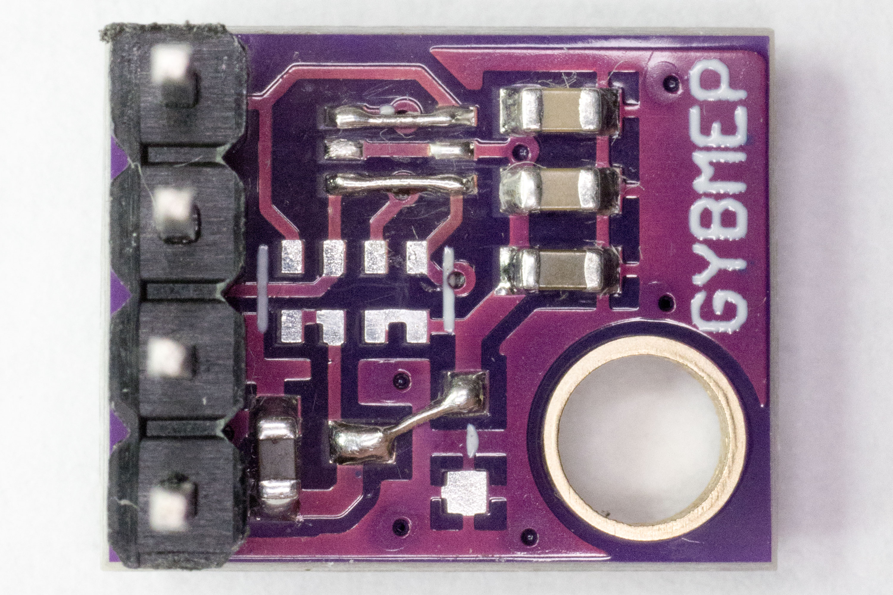
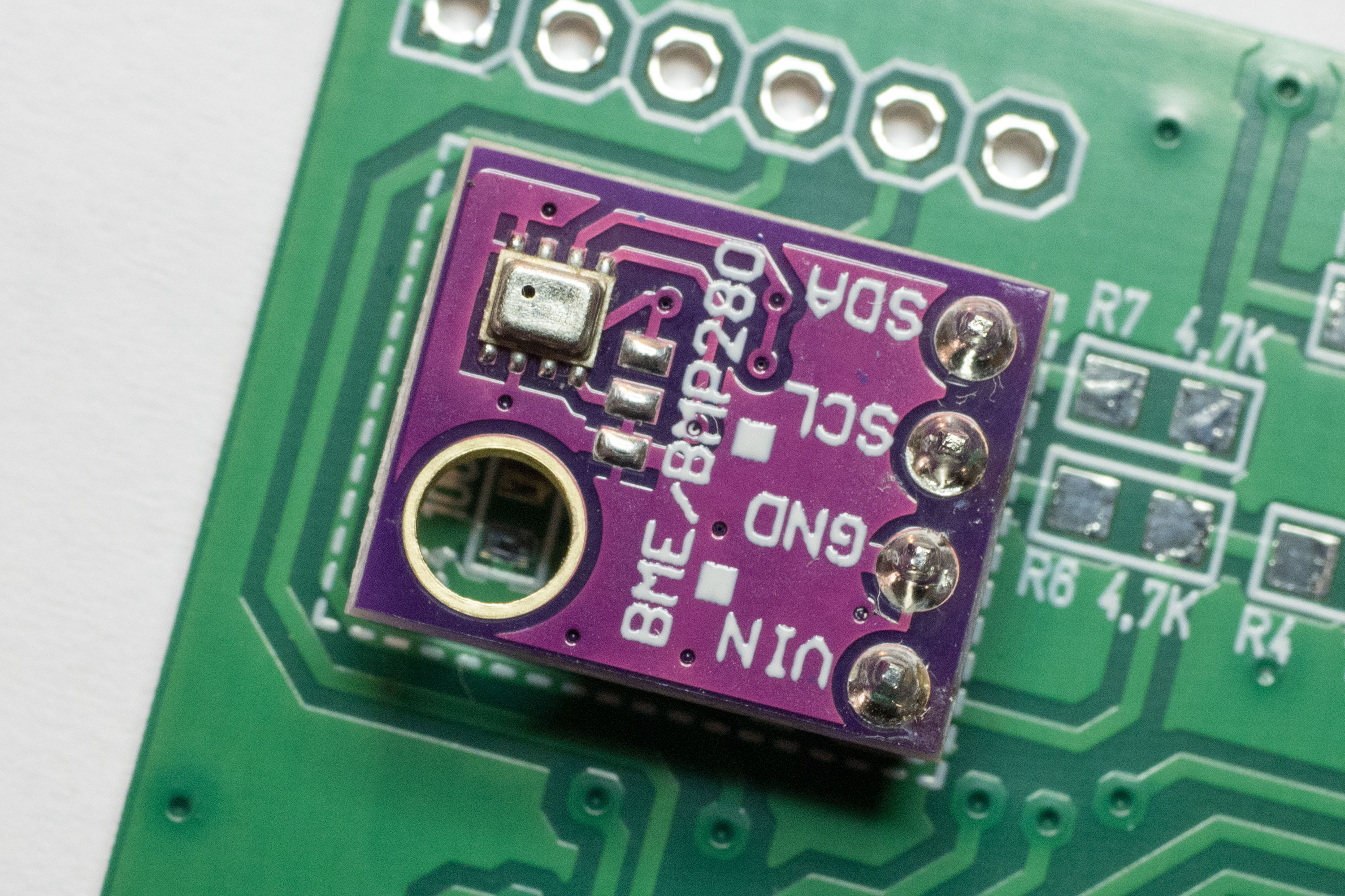
The heart of the circuit is an ATMega328P (IC1), which is clocked at 8MHz by a crystal (X1). To detect the pulse of the magnet, either the reed contact (S1) or the Hall sensor TMAG5231 or rather the Tunnel magnetoresistance sensor LF21235TMR (IC2) can be installed. Due to its design, the TMR sensor achieves higher sampling rates with lower current consumption and thus is the preferred choice. The RFM95W radio module (IC3) ensures LoRa connectivity. The red LED (D1) indicates the transmission status. Optionally, a BMP280 (IC4) can be installed to measure temperature and air pressure, alternatively via the I2C header (K4). The FRAM memory chip MB85RS64T (IC5) is used to store the LoRaWAN activation data and the counter reading. This is done every three transmissions to reduce the number of write cycles. In the event of a battery change, the stored information is restored. The ISP connector (K3) is initially used to program the bootloader. The serial interface on connector K2 can then be used to upload the firmware. Only 3.3V logic levels are permitted on both connections.
Assembly
With a few exceptions (C5, C6, C15, C16), resistors and capacitors are kept in the component size 0805 and can be soldered by hand with a little practice. The quartz crystal can simply be soldered onto evenly pre-tinned pads using hot air. The 2.0x2.5mm BMP280, on the other hand, is much more difficult to solder. However, if you do not want to solder the air pressure sensor directly onto the board using stencil, solder paste and hot air, you can use the I2C pin header (K4) to connect a standard module board. The voltage regulator and level shifter must be desoldered and bridged as shown in the picture in order to keep the quiescent current consumption low. I have also designed my own sensor board without a voltage regulator. Although the BMP280 also has to be soldered on there, replacing it is easier than soldering it directly onto the main board.
Mounting
To enable the air pressure to be measured and to prevent moisture from being suctioned into the housing, a 1 mm hole is drilled next to the antenna board and sealed again from the inside with a self-adhesive pressure equalization membrane. The main board and battery board are inserted into each other and initially connected at a solder joint. The two circuit boards are carefully pushed into the housing and the alignment is checked. The main board should be as parallel as possible to the housing wall so that the reed contact or Hall sensor / TMR responds properly. After correcting the alignment if necessary by pulling out the circuit boards and heating the solder joint, all connections are finally soldered. Be careful not to mechanically damage the solder pads on the circuit board. The main board and antenna board are connected with a 10 cm long U.FL cable. Once the bootloader has been flashed to the microcontroller, the board can be screwed into the housing. It is also possible to update the firmware while the device is still installed. The serial connector required for this is located on the top edge of the board.
Firmware
The firmware is using the PlatformIO build environment as well as Arduino and the MCCI LMIC library. All dependencies are resolved automatically. For use on the console PlatformIO Core can be downloaded, alternatively VS Code with PlatformIO as plugin can be used as IDE.
After downloading the firmware from Github, we change to the corresponding directory on the console.
cd lora-raingauge
The first step is to burn the bootloader into the ATMega328P once. This requires an AVR-ISP (e.g. USBasp) with a 6-pin connector (K3), which operates at a level of 3.3V. Caution: A higher voltage will destroy the RFM95W. The programming process is performed as follows:
In the src directory the file config.h.example is now copied to config.h and opened with any editor. The OTAA activation data (see below) corresponding to the LoRaWAN stack to be used (e.g. The Things Network or Chirpstack) is stored here. The firmware can then be compiled and uploaded via the Arduino bootloader using the serial interface (K2). Again, only 3.3V level is permitted. The process is done via the following command:
After a successful upload, the rain gauge starts and switches to deep sleep mode first. It wakes up as soon as a defined period of 15 minutes has elapsed or the button in the battery compartment is pressed (possible once a minute). If there is no session, the device initially performs an OTAA activation on the LoRaWAN stack and then transmits the measurement data. An active LED indicates data transmission. If the activation fails, the LED flashes for a few seconds. The microcontroller then goes back into deep sleep mode. After waking up, data transmission (or activation if failed) starts again. The debug output on the serial interface can be viewed with the following command:
The sensor saves its activation data and the rainfall counter value in the FRAM from time to time so it can be restored from there after a battery replacement. To repeat the OTAA activation, the button in the battery compartment can be held down for a few seconds when inserting the batteries. Furthermore, a checksum of the configuration file is compiled into the firmware and stored in the header of the FRAM data for later comparison. Flashing the firmware with a modified config.h therefore also results in a reset of the data.
Configuring the network stack
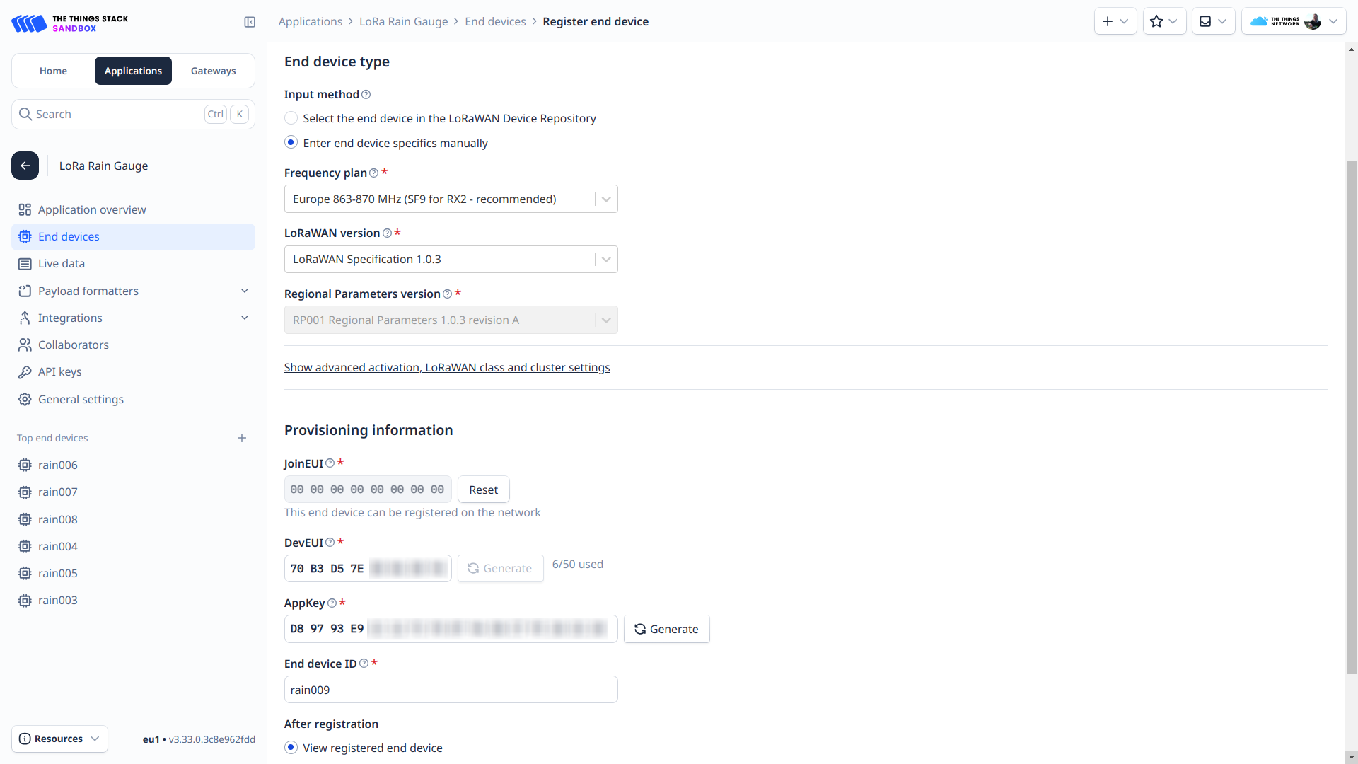
First, a new application must be created in the LoRaWAN stack interface. Under this application, the uplink payload decoder is then added in the form of Java script, which converts the incoming binary data into the human-readable JSON data format. The appropriate code for TTN and Chirpstack can be found in the repository under docs/payload-decoder.js. The packet size sent varies depending on whether a BMP280 temperature / air pressure sensor has been detected or not. This is also automatically taken into account in the payload decoder.
Any number of suitable end devices (nodes) can now be registered under this application. In the Things Network, "Europe 863-870 MHz (SF9 for RX2 - recommended)" is selected as the band plan. SF12 would also be possible, the configuration is synchronised as part of the Over-The-Air-Activation (OTAA). The LoRaWAN version is set to 1.0.3. This is specified by the LMIC library.
The AppEUI or JoinEUI can be filled with zeros, DevEUI and AppKey can be generated in the stack user interface. This data is then entered from the interface into the config.h mentioned above. It is important to ensure the correct byte order. The former values are kept in little-endian (LSB) order, while the AppKey uses the big-endian (MSB) order.
You can now proceed with compiling and uploading the firmware. Activation and transmitted data packets can be tracked in the network stack log, and the decoded payload can also be viewed.
It is also possible to adjust the transmission interval and the rain counter at runtime by sending a corresponding downlink message. Here, fPort 1 is used for the interval in seconds and fPort 2 for the counter value. Both are transmitted as an unsigned 16-bit integer (MSB first). For example, the hexadecimal value 0384 would be sent to fPort 1 for a 15min (900sec) interval. The option to transmit a downlink packet can be found in TTN under "Messaging" or in Chirpstack under "Queue".
Data visualisation
To store and visualise the measurement data, I use a Telegraf-InfluxDB-Grafana stack. I have prepared a sample configuration for this using the container virtualisation Docker, which is ready to go within a few minutes. Telegraf retrieves the decoded JSON data via the MQTT integration of the Things Network and writes it to the InfluxDB database. Grafana is already provisioned with a suitable dashboard. After downloading the repository from GitHub and entering the MQTT connection data, the containers are created using Docker Compose and Grafana can be accessed via a web browser. The exact steps are described in the corresponding readme.
Battery runtime
To determine the battery runtime, the power consumption was measured using the Power Profiler Kit 2. The screenshots below show the power consumption for data acquisition and transmission over a period of about 6s at SF7 and the deep sleep over a period of one minute.
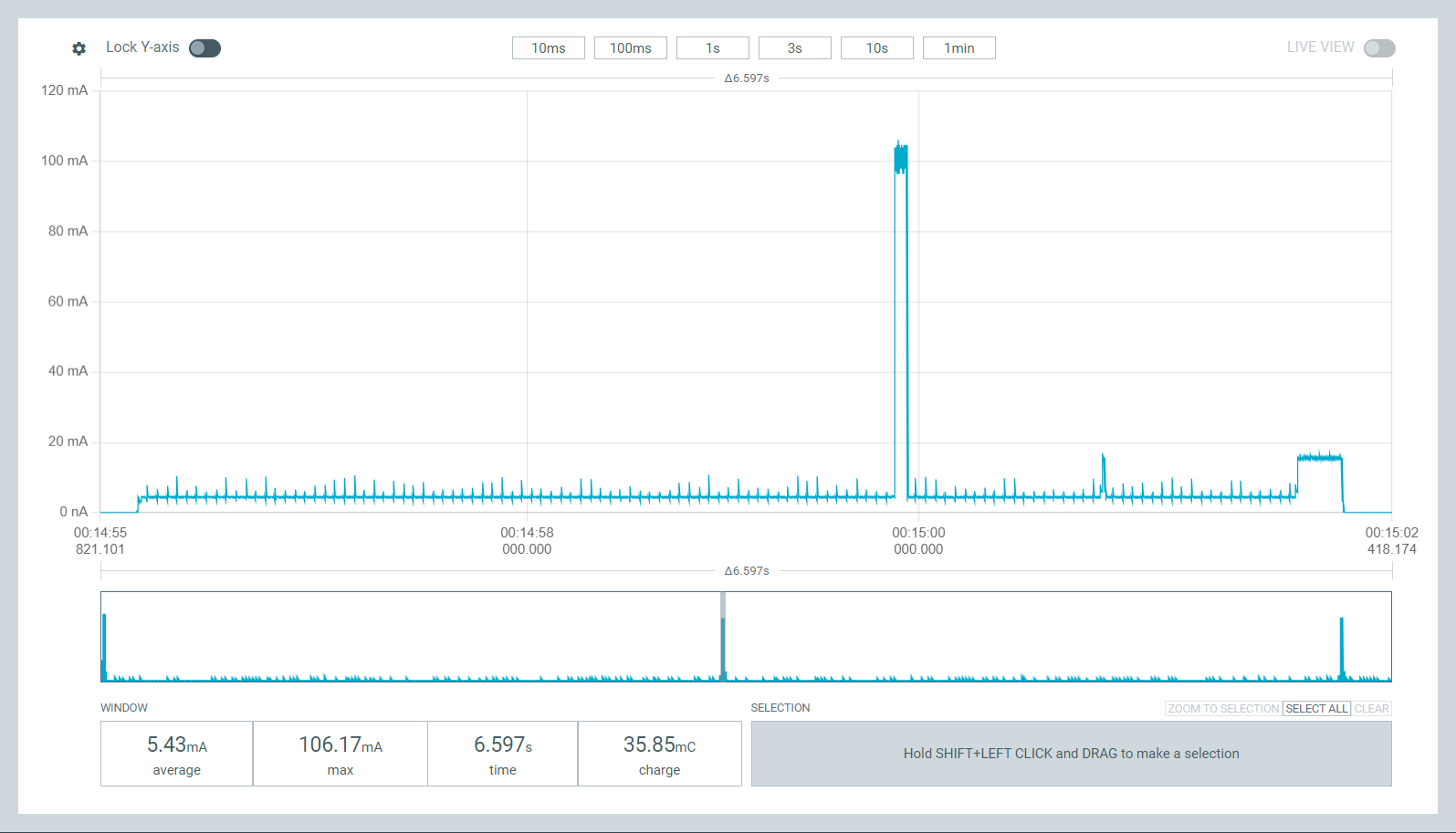
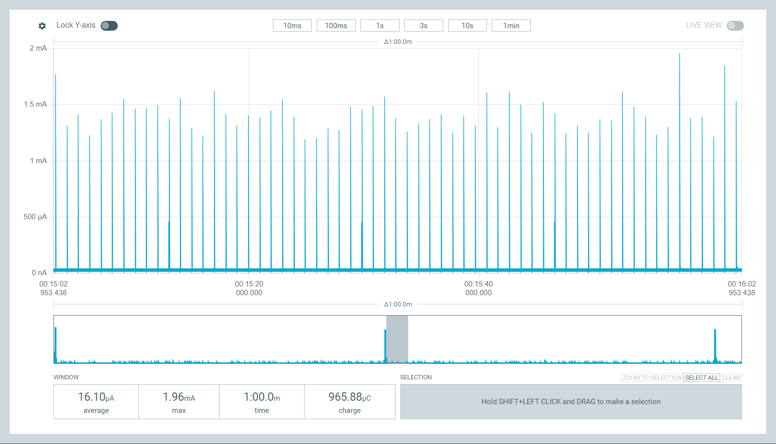
The software outputs the charge drawn in Coulomb. If we look at this over a period of one hour, the circuit will carry out four measurements (42.3mC/6s - 169.2mC/24s each) at 15-minute intervals and spend almost one hour (868.3µC/min - 52.1mC/h each) in deep sleep. Since the duration of the measurement is negligible, we sum both values to simplify the calculation and get a charge of 221.3mC/h. This corresponds to 0.0615mAh/h. With a battery capacity of 2000mAh, this results in a runtime of 1355 days or 3.7 years.
Notes
When using the ATMega328P, please note that the datasheet only specifies it down to 2.7V. However, the newer ATMega328PB can be used as an alternative, which should work reliably at 8MHz in the entire temperature range down to around 2.1V. Corresponding discharge curves show that the assumed capacity of 2000mAh can realistically be provided by an alkaline manganese battery at a discharge current ≤100mA with this final discharge voltage.
The MCUs internal watchdog is used for timing in deep sleep mode. Unfortunately, this uses an RC oscillator, which shows deviations depending on the operating voltage and ambient temperature. If necessary, the interval can be corrected using an uplink packet.
For current measurement, the Power Profiler Kit 2 was supplied from an external linear power supply. In earlier revisions however, oscillations could be observed which were caused by the pulsed operation of the Hall sensor. Various reports on this phenomenon can be found in the TI Forum. For this reason, a tantalum capacitor was added in board version 1.2, the ground plane was optimized and the layout was extended to four copper layers. The additional inner layers carry a continuous 3V operating voltage and ground. As a result, no more abnormalities could be detected.
In some cases, deviations in the ceramic resonator led to failing joins and downlinks. This was resolved through the software by setting larger tolerances in the LMIC stack. Nevertheless, in revision 1.3 a quartz crystal was used in order to achieve a higher clock accuracy.
Downloads
- Schematic (PDF)
- Bill of materials (PDF)
- Layouts and BOM
- Layout of the main board in Gerber format
- Layout of the battery board in Gerber format
- Layout of the antenna board in Gerber format
- Layout of the sensor board in Gerber format
- Firmware at GitHub
- Docker Telegraf-InfluxDB-Grafana stack at GitHub
- Leaf guard (Thingiverse)
- Mounting plate with 90 degree angle for brick wall or flat roof (Thingiverse)
There might be some boards and spare parts left from development. Drop me a message if interested.
Publications
- Hackaday: A LoRa Rain Gauge From The Ground Up
- AATiS Praxisheft 35: Regenmesser auf LoRaWAN Funktechnologie umgebaut
More interesting projects
- LoRaWAN rain gauge (icplan.de)
- rtl_433 - Decoding the original transmitter using an SDR stick (github.com)
- Decoding the TFA 30.3161 rain transmitter (via Raspberry Pi Pico) (blog.heimetli.ch)
- Rain gauge for ioBroker (Source for calculating the amount of rain per pulse) (forum.iobroker.net)
Lizenz
The project may be freely used and modified for private use, but the author's name must be retained (CC BY-NC-SA).